Instant Box Camera - Update
I've been busy this weekend, trying to make progress on the Instant Box Camera project. I'm happy to report that it's coming together, albeit slowly. This update is a quickly hurried assortment of images, for which I'll provide descriptions.
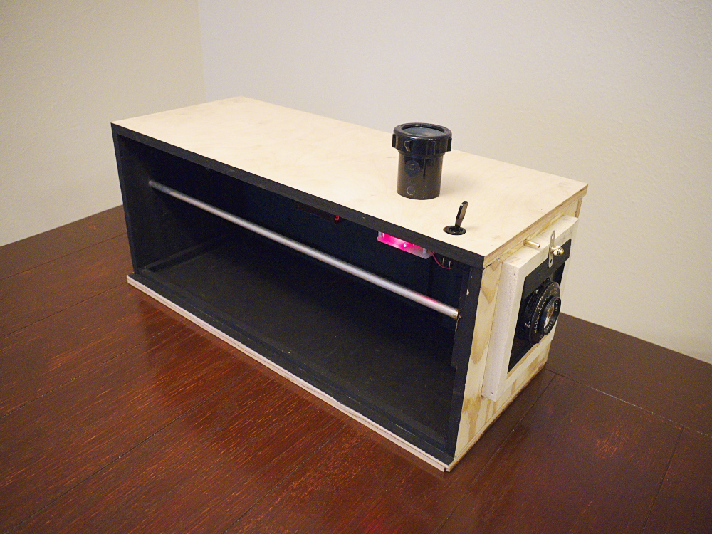
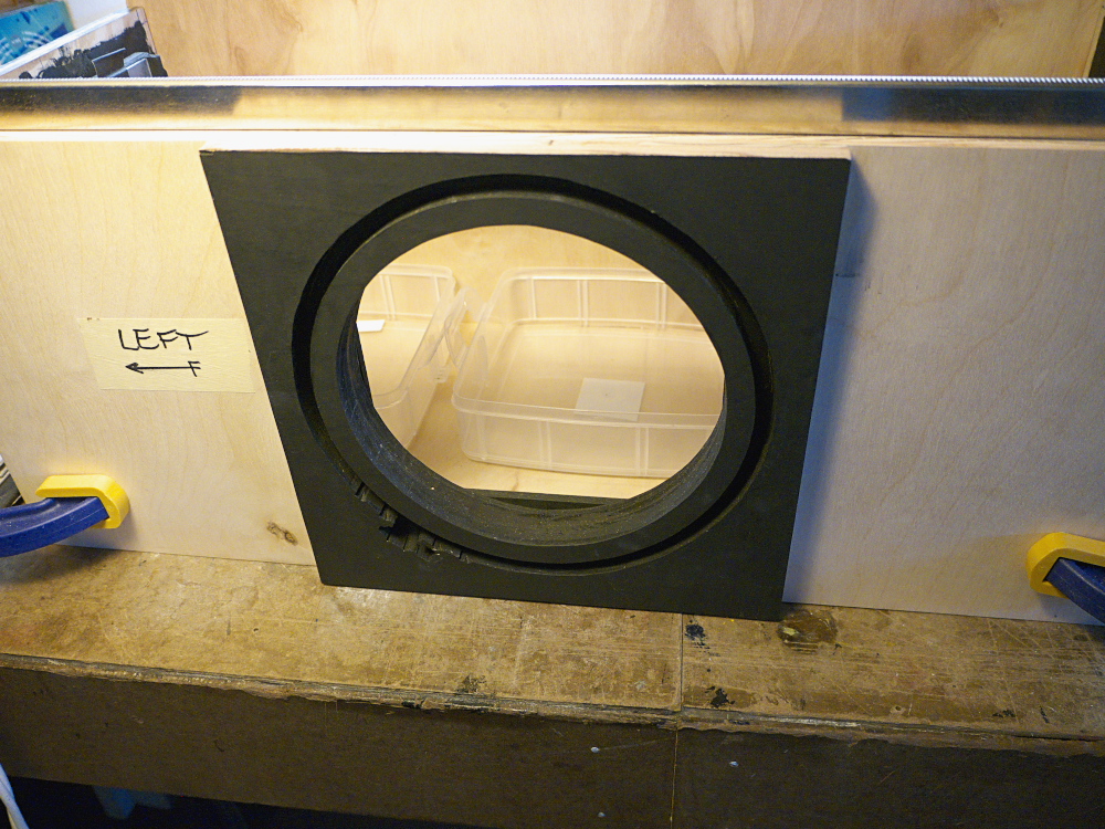
1. Assembly: As you can see from the top image, the box is assembled, with the right side panel removed to show the interior; this side panel will be removable to gain access to the interior, mainly for removing the trays of liquid chemicals. The red LED circuit is active and working, powered by two AAA dry cells, mounted in a holder that's Velcro-attached to the top panel. The large automotive-style switch on top activates the LED.
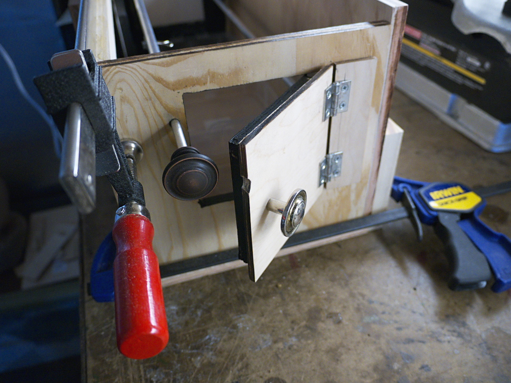
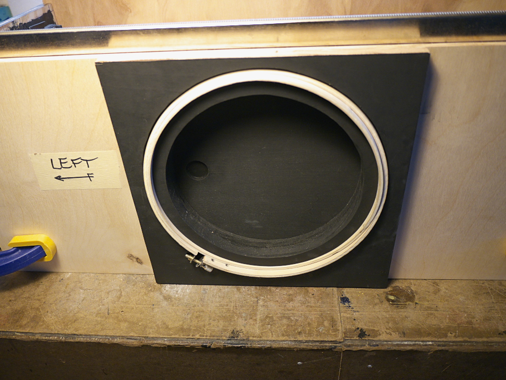
2. Rear door detail: Surprisingly, it's light-tight, at least by flashlight inspection! Though these shots were made before the interior was painted flat black. I still need to attach a locking device to the door. The groove cut in the edge of the door is to prevent interference with the focusing rod.
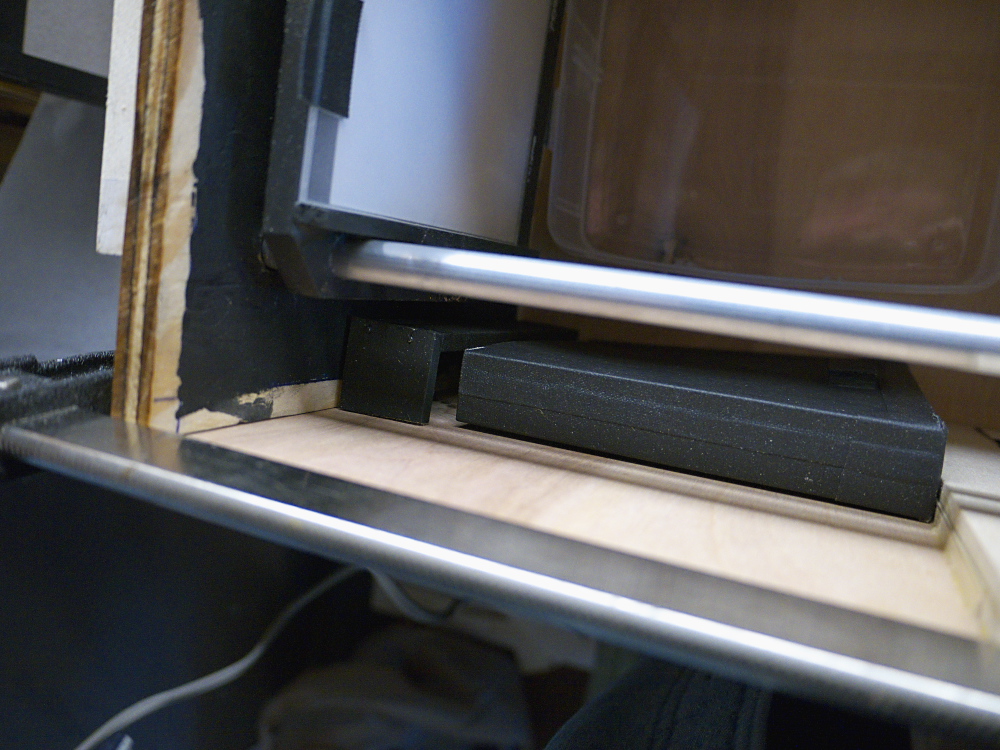
3. Paper Safe: I located the paper safe box in the front left corner, easily accessed via my right arm in the arm sleeve.

To gain access to the paper safe, it's first slid toward the rear of the camera, away from its retaining bracket:
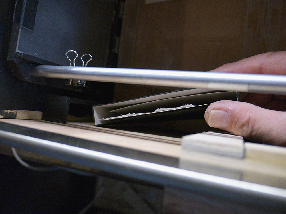
Then it's rotated so the opening is facing up, where I can gain access to the paper negatives. I have a cardboard divider inside the box, separating the grade 2 glossy RC paper, used as negatives, from the multi-grade luster finish paper used for the final prints.
4. Arm Sleeve: I had the black fabric sewn into a double-thickness arm sleeve, with an elastic cuff and hemmed edge where the sleeve attaches to the box. I'm using a set of wooden sewing hoops to attach the sleeve to the box, with the fabric being captured between the smaller and larger hoops:

There's a groove built around the arm sleeve opening:
The sewing hoops will fit inside this groove snugly, then a cover piece of thin plywood will be screwed down to secure the sleeve in place:
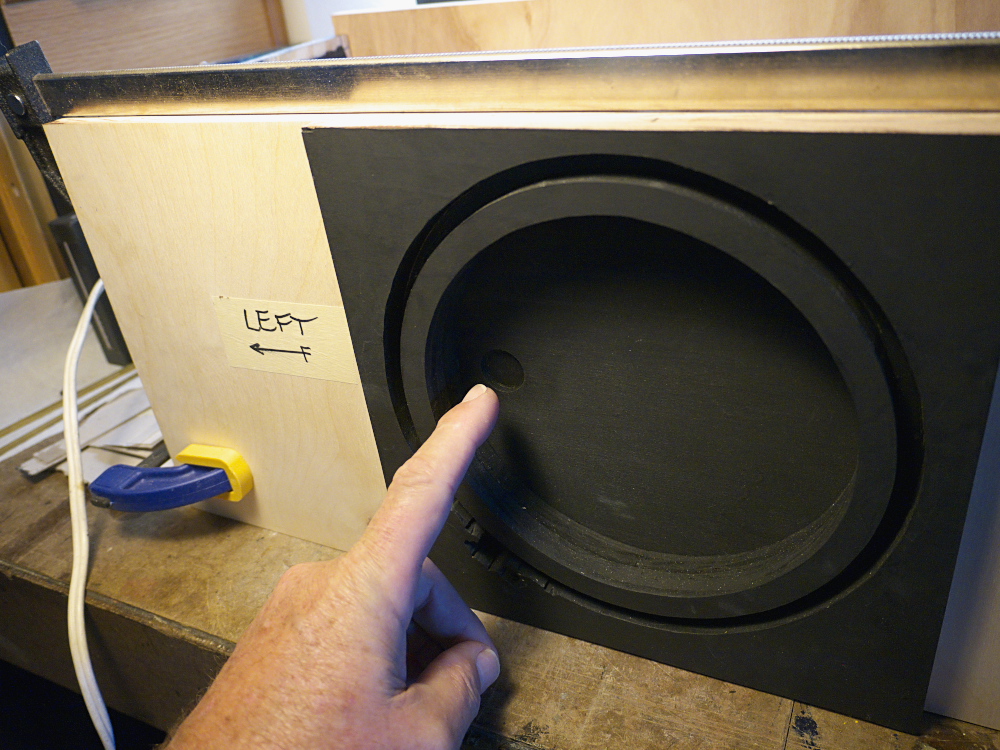
5. Arm Sleeve Door: I wanted to have a closing, light-tight access door at the base of the arm sleeve where it enters the box, so I can load up a paper negative into the camera and then remove my arm so I can attend to the subject during the exposure. I built this sliding door of thin plywood. There's a round recess on the outside of this door, to assist in sliding it open:
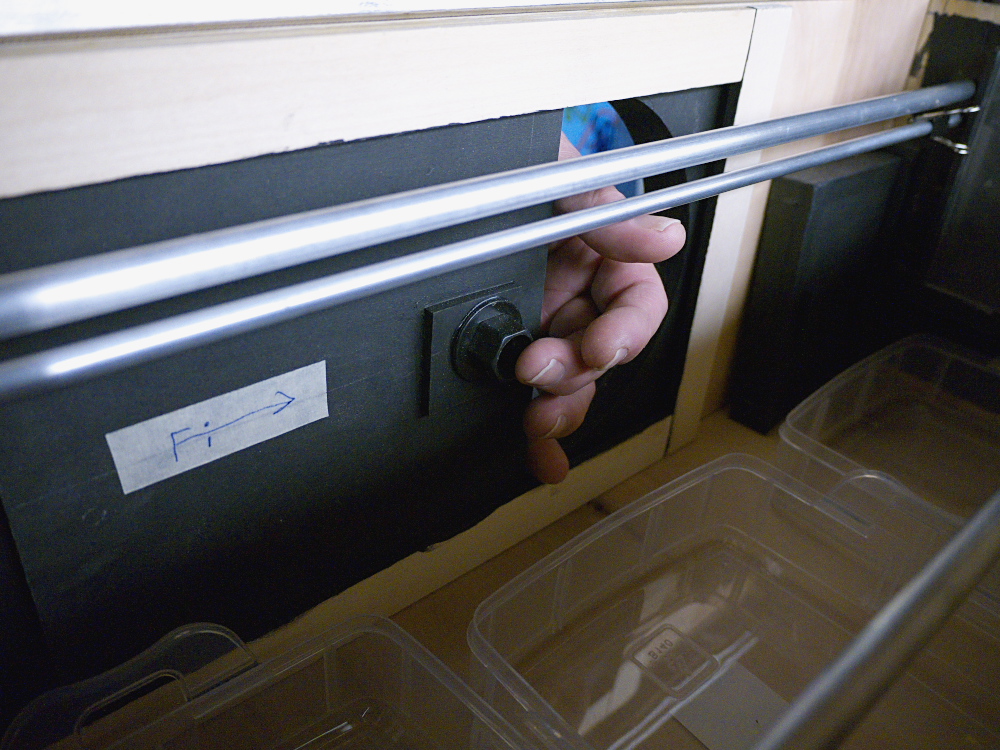
While on the inside of the door there's a protruding plastic knob that I can reach to slide the door closed:
6. Viewing Port: The viewing port atop the box, used to monitor the paper development, is a piece of plastic plumbing fixture. A red filter will be installed in this port, to help cut down on any light leaks:
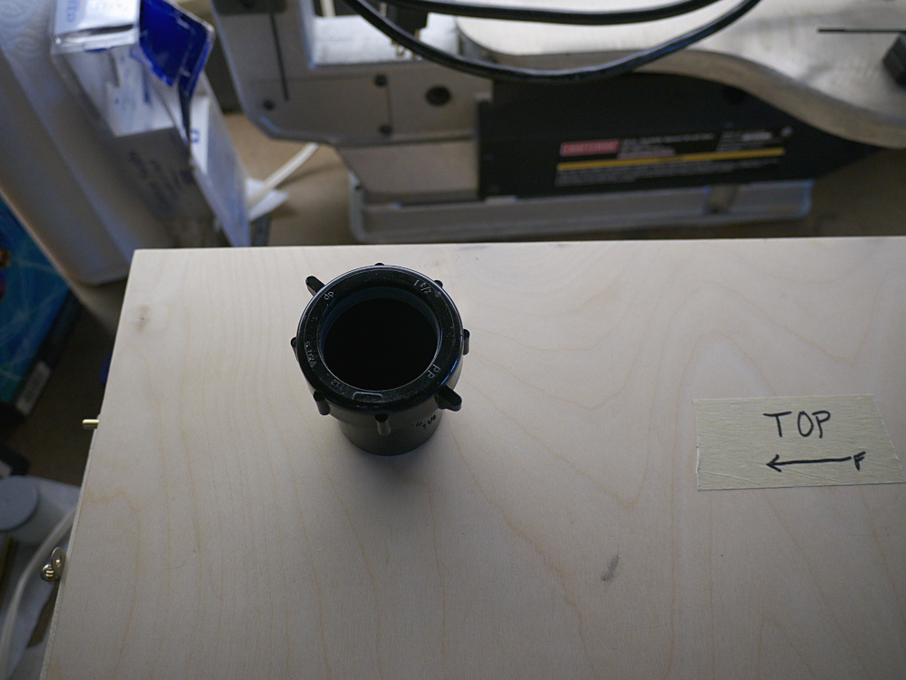
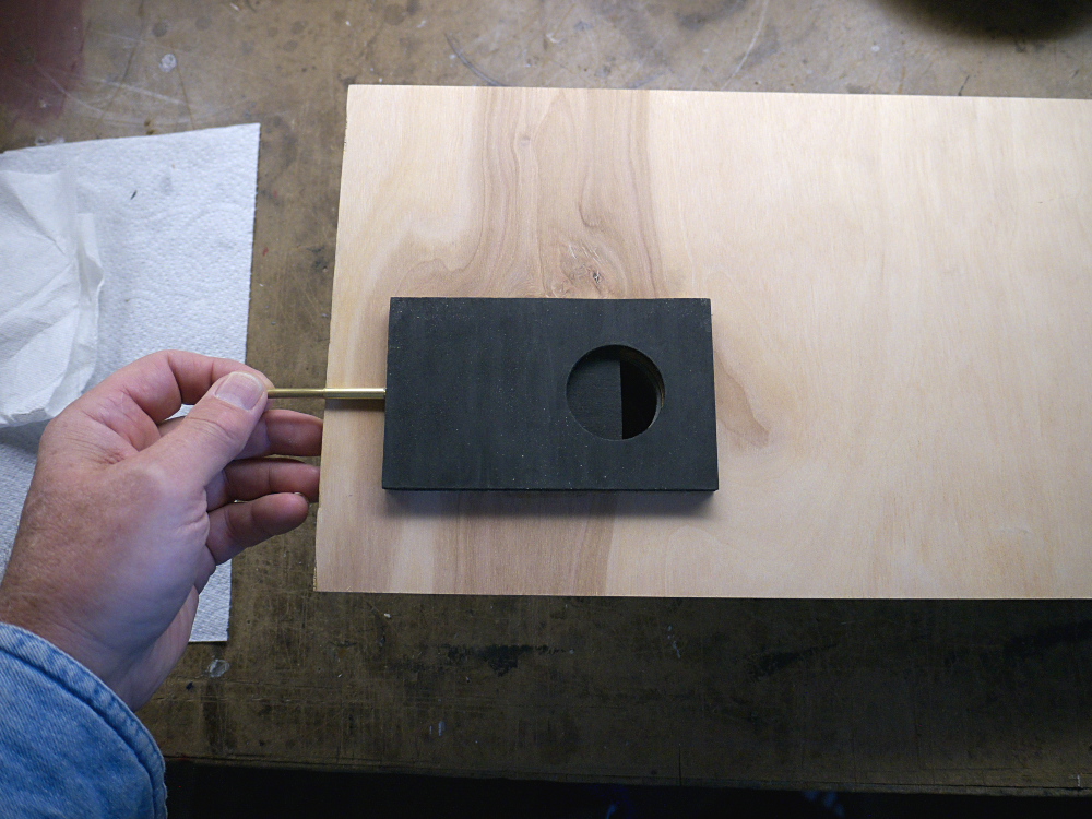
Based on tests I conducted last month, I know that my eye has to be pressed tightly against the port before opening the inner shutter, even with a red filter on the port. Here's a detail of the shutter mechanism, on the inside roof of the box, actuated by a brass rod protruding out the front, above the lens mounting bracket:
The purpose for the red LED circuit is to provide illumination inside the box, that won't fog the photo paper yet permits me to examine the paper as it develops. I mounted the LED, its white diffuser and battery holder near the front right side roof of the box, in order for it to not interfere with the focusing bracket.
What's Next: I have yet to finish gluing light baffle sticks to the removable right side panel, then paint it black. Then a set of brackets with machine screws gets mounted on the box opening at the front and back edges, which will extend through holes in the removable right side panel, to secure it via thumb screws. Also, a 1/4-20 tripod bushing still needs to be mounted to the bottom of the camera. And the rear door needs a latch mechanism installed. Then the arm sleeve and sewing hoops gets installed. Afterwards, it'll be time to test the box camera, first for fogging from light leaks, then a first round of test exposures. Perhaps next week I'll have good news to report. Stay tuned.
posted by Joe V at 8:27 PM
![]()
![]()

5 Comments:
Very interesting project. I await the results of your photos.
Bravo! An excellent design, I think - very well-considered. (:
Re: monitoring developing, I wonder how useful an old IR-sensitive digital camera sensor might be for such an application. any old early 2000's Sony camera with "Nightshot" mode would be able to see with a great deal of detail in the weak red light thrown by your LED arrangement. If it proves difficult to properly see your progress with a lot of red filtering on your viewport, it might be something to consider.
It is hard to separate the art from the engineering and the madness with this one - that's a good sign. All together though, this device is poetry. I wonder if this was a similar road travelled in the development ('scuse the pun) of the Polaroid instant system?
That looks like a long object to be supported only by one tripod screw/socket. You may end up with chemical spills. I would consider a X stand like waiters use in restaurants, that easily fold up for carrying, and open with one hand. I'm curious to see if the LED will fog the paper, of if you are going to need a filter over it.
Phil, I've already tested the red LED. It does fog the paper very slightly if placed with about 5" directly above the paper; but placing a 1/8" thick piece of frosted white plastic as a filter causes no fogging, even after three minutes of exposure.
Your thoughts regarding the wobbliness of the mount are well taken; I've yet to add a tripod bushing to the bottom of the box, thinking instead I might make a lower platform base that's more secure.
Post a Comment
<< Home